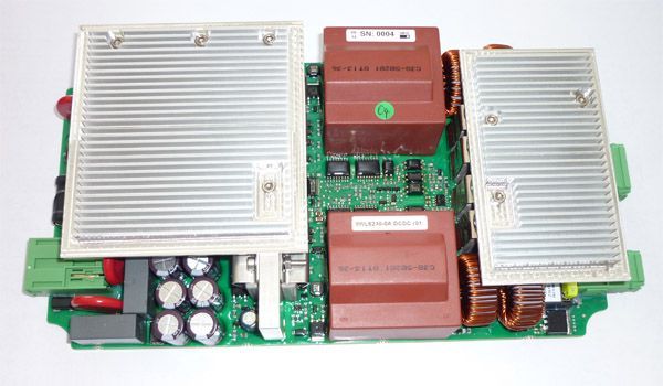
Range of application of the DCDC power supply with battery buffering
Contact wire voltages of 600V DC to 750V DC are a widespread standard in local rail passenger transportation systems for the power supplies of electric traction vehicles. The electric traction vehicles (e.g. streetcars) are equipped with current collectors that contact the overhead contact line during travel in order to be able to continuously supply the vehicle with power. On the track, e.g. on the catenary masts, there are various electrical and electronic applications, such as disconnect drives, which are responsible for various switching and control operations during rail operation. These require their own power supply, which could be ensured via 230V AC, but this would be associated with additional cabling effort on the track. The development of a DCDC 600/750V DC to 24V DC power supply with optional accumulator buffering, briefly described below, aimed at supplying the electronic switching and control elements on the contact line with power directly from the overhead contact line and to ensure operation without contact wire voltage for a certain period of time by means of the optional accumulator buffering.
Functional groups of the DCDC power supply with battery buffering:
- Implementation of a multi-stage overvoltage protection:
- by the parasitic resistance of a longitudinally connected storage choke
- by varistors
- by further longitudinal elements
- by transverse varistors for discharge
- Inrush current limitation by mosfets, which control the charging current of the capacitor bank
- Due to the railway standard, increased spacing in the layout, therefore use of 2 H-bridges connected in series on the primary side.
- Customised transformers and storage chokes to meet the 700VDC requirements (up to 1000V DC at max. 5min duration) and to minimize core losses.
- Temperature-dependent charging curve
- Active rectification on the secondary side to achieve high efficiency
- Active charge state monitoring of the buffer batteries by microcontroller (At-mega 165P)
The DCDC converter complies with EN 50121 and EN 50124 railway standards for overvoltage and noise immunity and EN 60721-3 for environmental and storage conditions. Circuit diagram design and PCB layout were carried out with Altium. The development time including the necessary certifications, from the creation of the specification to the release by the customer, was 15 months.
